Ultra Slim

ESN Series

  • Ultra thin
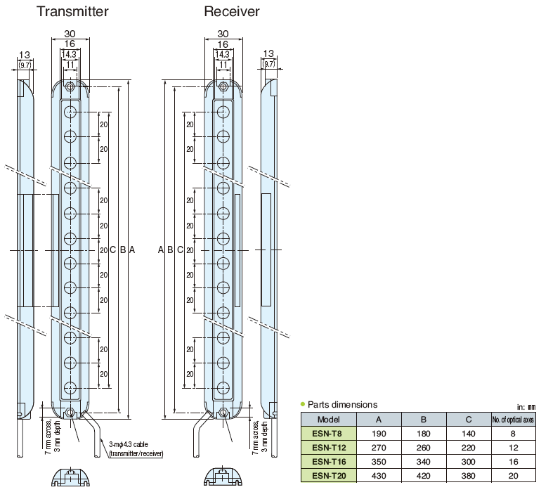
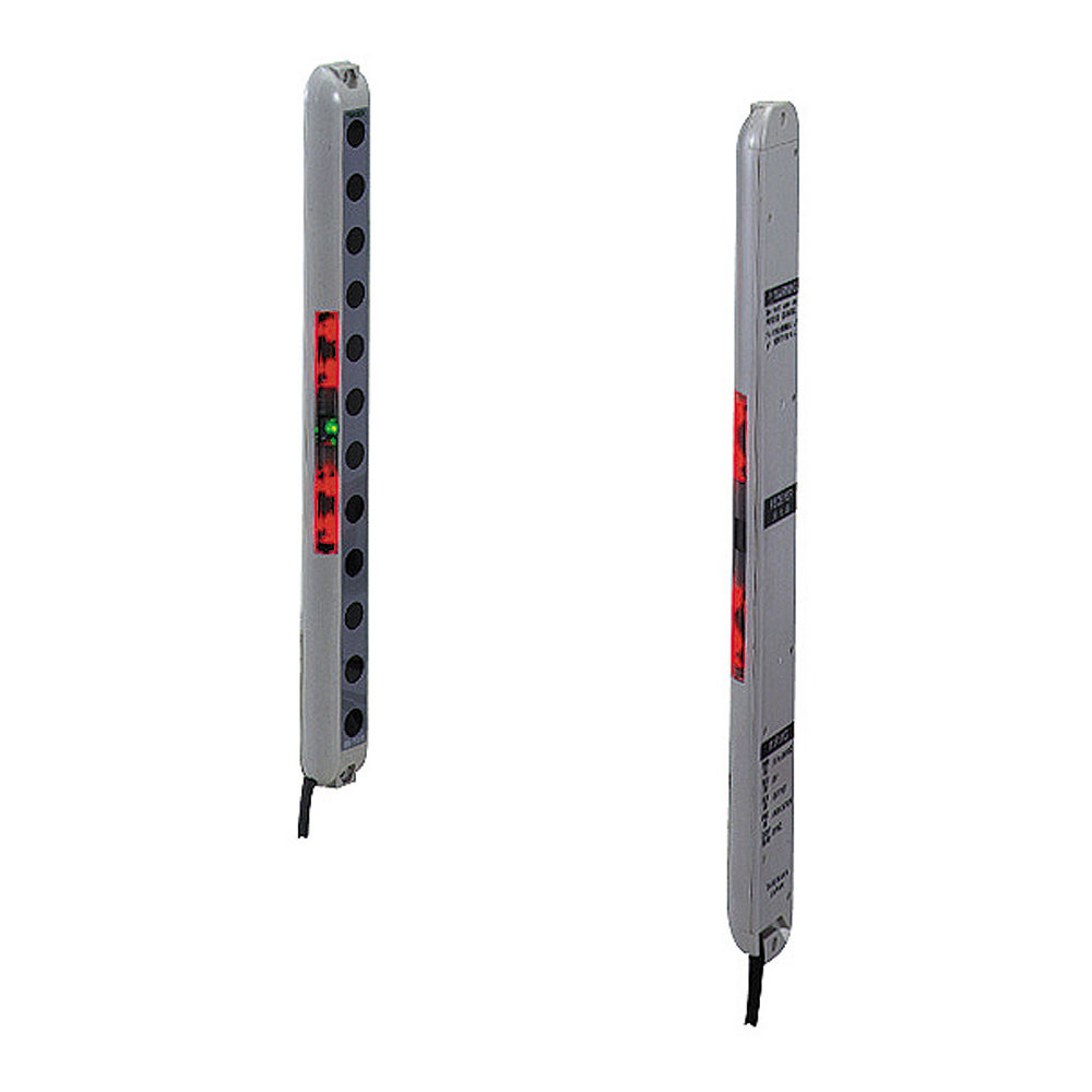
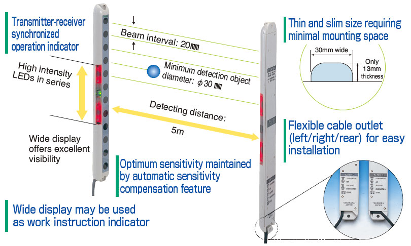
    Slim type of only 13 mm thick and 30 mm wide never affecting work efficiency
  • High intensity red LED indicator
    Large operation indicator of high intensity LEDs in series offering superb visibility, may double as work instruction indicator
  • Objects as small as φ30mm detected
  • Automatic sensitivity compensation feature
  • Anti Interference feature
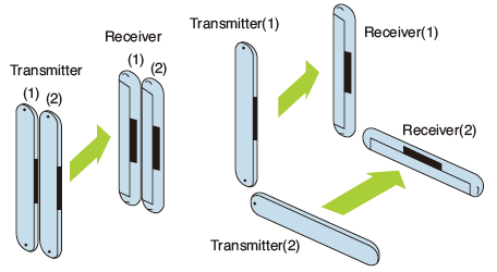
    Allowing adjacent mounting of 2 units for wider range of applications
Contact us about this series

ESN Series

Model Detecting width Beam interval Detection object Output mode Protective structure  
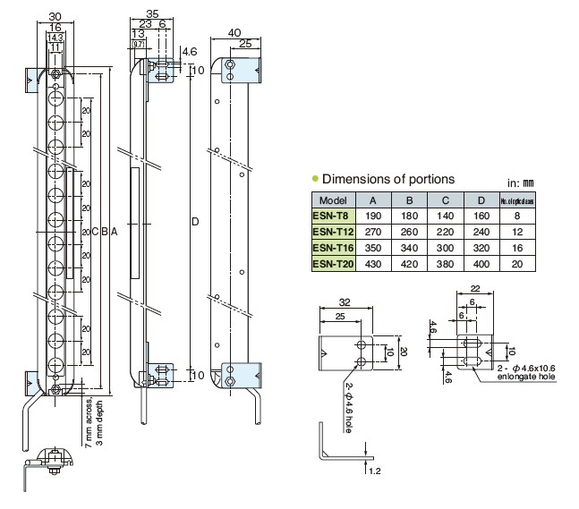
ESN-T8 140mm 20mm Opaque φ30mm or more NPN IP40
Contact
ESN-T8PN 140mm 20mm Opaque φ30mm or more PNP IP40
Contact
ESN-T12 220mm 20mm Opaque φ30mm or more NPN IP40
Contact
ESN-T12PN 220mm 20mm Opaque φ30mm or more PNP IP40
Contact
ESN-T16 300mm 20mm Opaque φ30mm or more NPN IP40
Contact
ESN-T16PN 300mm 20mm Opaque φ30mm or more PNP IP40
Contact
ESN-T20 380mm 20mm Opaque φ30mm or more NPN IP40
Contact
ESN-T20PN 380mm 20mm Opaque φ30mm or more PNP IP40
Contact

More Info

Transmitter-receiver synchronized operation indicator

Adjacent or face to face installation of two pairs of sensors will not cause interference.

Adjacent or face to face installation of two pairs of sensors will not cause interference.

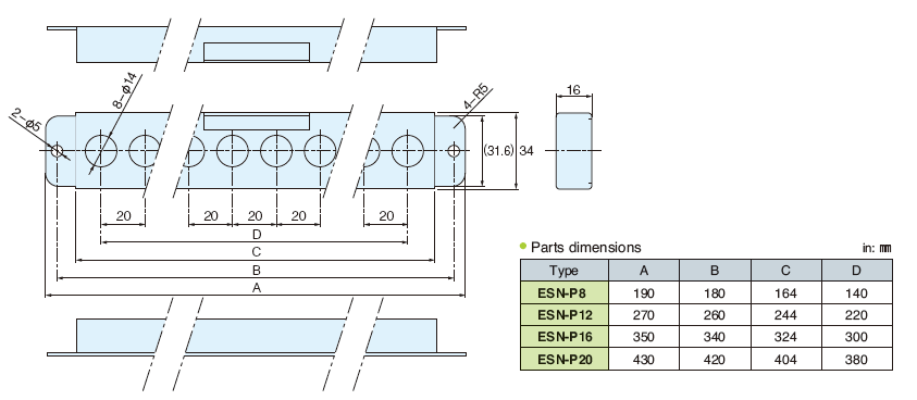
Protective cover

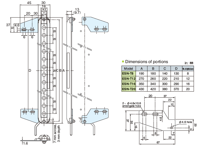
With mounting bracket model ES-BF

With mounting bracket model ES-BL

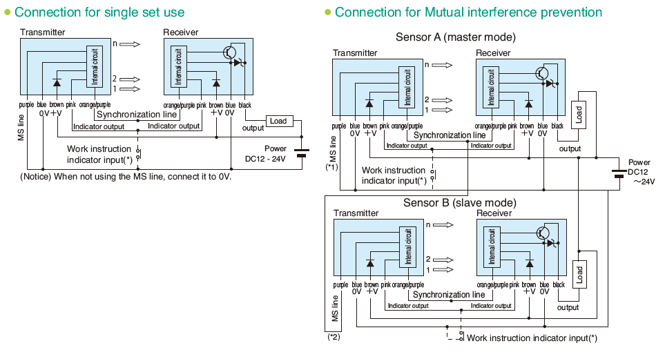
NPN output

  • In the condition of load short circuit or overload, the output transistor turns off.
    Check the load condition before restarting.

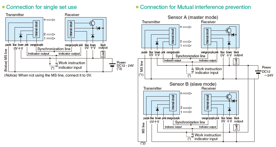
PNP output

  • (*1) Connect the MS line (purple) of the transmitter of either (A) of the two sensors to the ground line (blue), which sets the operation mode of this sensor (Sensor A) to master (M mode).
  • (*2) Connect the MS line (purple) of the transmitter of the other sensor (B) to the synchronization line (orange/purple) of Sensor A, which sets the operation mode of Sensor B to slave (S mode).
  • (*3) When using different power supplies for the transmitter and the receiver, or for the master and slave sensors, be sure to use the common 0V for each unit.
  • * When using two sets as a pair, wire so that the operation mode of either of the two will be master and of the other will be slave.
  • * Do not connect the synchronization lines (orange/purple) of Sensors A and B to each other.

Subscribe

Sign up to receive latest news releases and product updates