After aligning all of the beams using a voltmeter and the beep sound function, and achieving optimum alignment voltage of +2.7V, please follow these steps:
Step 1.
Fit the polycarbonate cover on the tower housing the Transmitter units.
Step 2.
Place the polycarbonate cover for the Receiver Tower approximately 15cm in front of the Receiver Tower in line of the beam path, so that the beam passes through both polycarbonate covers (you may need to hold this if it is windy or the ground is unstable).
Step 3.
Leaving the sounder/beep function "ON", fit the supplied lock spacer (rubber bung) into the Receiver unit as follows, ensuring you are not blocking the beam path.
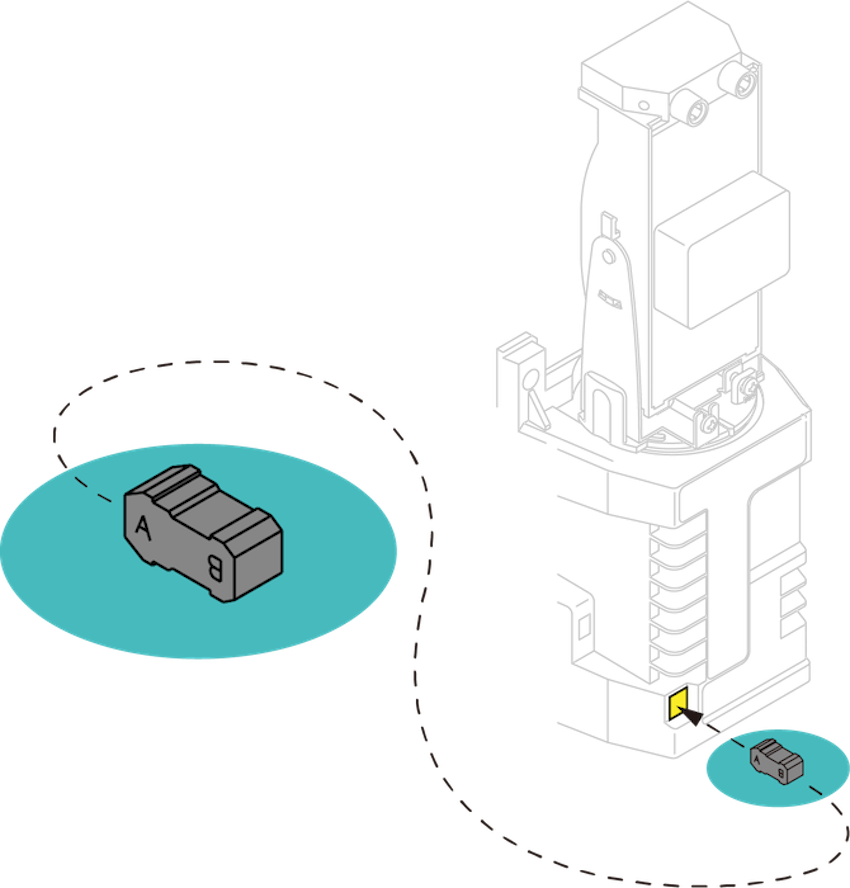
You should hear a long single beep confirming that the auto-gain is now set (if you hear a staccato/rapid beep, there is a problem, remove the lock spacer and try again, making sure you aren’t blocking the beam path).
Note... if you still have the voltmeter connected, you will notice that the alignment voltage has now dropped, perhaps by as much as 30%; this is a normal and intentional function of the Receiver unit.
Step 4.
Once you have repeated the process with all of the receivers, fit the cover to the Receiver Tower and secure the tower tops.
And You're Done!
If power is interrupted at any time the receiver remembers the auto-gain setting provided the lock spacer isn’t removed. If you have left the beep/sound switch on, and you can hear a tone coming from the receiver after 5 minutes or more (maybe even after a few years) it means the lock spacer is loose and needs to be refitted.
Following this procedure exactly ensures the system has the best opportunity and capability to cope with environmental difficulties.