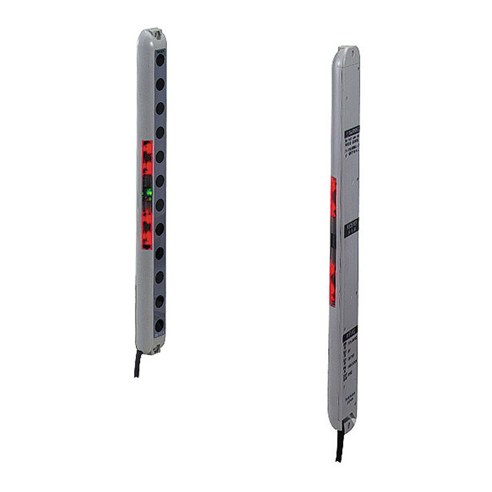
Ultra Slim
ESN Series
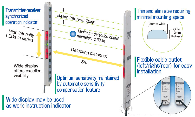
- Ultra thin
Slim type of only 13 mm thick and 30 mm wide never affecting work efficiency - High intensity red LED indicator
Large operation indicator of high intensity LEDs in series offering superb visibility, may double as work instruction indicator - Objects as small as φ30mm detected
- Automatic sensitivity compensation feature
- Anti Interference feature
Allowing adjacent mounting of 2 units for wider range of applications